Real-time X-ray radioscopy
X-Ray radioscopy measurement apparatus
|
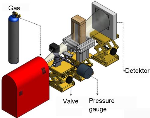
The foam characterisation tool built is shown in Fig 1. The
imaging system consists of a closed, air-cooled microfocus X-ray source (spot size 5±50µm depending on voltage and
current) from Hamamatsu with up to 150 kV voltage and 500µA current, corresponding to a power of 75 W, and a flat
panel detector (area ~ 120x120 mm2, 2240x2368 pixel2, pixel-size: 50µm), also from Hamamatsu. The maximum acquisi-
tion rate of the detector is 9 pic/s. In comparison to the synchrotron X-ray based imaging previously used for investigating
metallic foams this X-ray system is different in twofold respect: First, the X-ray intensity of a microfocus source is much
smaller than that of a synchrotron source resulting in limitations with short exposure times imposed by the signal-to-noise
ratio. However, in our measurement configuration the intensity is enough to get satisfactory contrast for many applications,
even for real-time picture acquisition at moderate image acquisition rates of 1 Hz. Only for very fast imaging use of synchrotron rays is
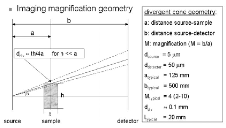
mandatory. Secondly, we have a divergent cone beam geometry instead of a parallel one when using a point source (see Fig. 2).
This type of projection is described in detail for tomography applications by Kak et al. and for radioscopy by Mery et al.
One implication is the possibility to adjust the required magnification M. It is given by M = b/a (a is the distance between
source and sample and b between source and detector). Useful M's can be as high as 10 for our configuration. To find the
best imaging parameters with, e.g., the best spatial and time resolution and the desired magnification other factors have
to be considered such as the sample geometry, the source pitch (d source » 5 µm), the detector pitch (d detector = 50 µm)
or the divergence distortion d div » th/4a for h bigger a. At a given magnification a higher distance between source and
detector will reduce d div, but the intensity will be also reduced as I ~1/b2 ~ 1/M2. The usual parameters selected for
experiments are:
tube: U = 100 kV, I = 100µA
geometry: a = 125 mm, b = 900 mm, M = 4, t0 = 10 mm, h0 = 4±5 mm, l0 = 15±20 mm
F. García Moreno, M. Fromme, J. Banhart, Advanced Engineering Materials 6:416-420, 2014