SEM and TEM analysis
|
For a microstructural analysis of the particle arrangement at the solid-gas interface of films and foams a SEM, consisting
of an ultra-high-resolution GEMINI© field emission column, called CrossBeam 1540 EsB© and manufactured by Zeiss, is used. This
workstation additionally unifies a Focused Ion Beam (FIB), composed with a high performance gallium ion cannon, which is used
to cut fine lamellas out of the sample surface to characterise the oxide layer using a TEM. An example of such a lamellae
during the liberation process is presented on the right side. To protect this layer during
milling a 1 µm thick carbon layer was deposit on the surface before starting the process. The following milling steps are
performed with a 30 keV Ga ion beam of 10 nA, 2 nA and 200 pA to prepare a lamella of 10 µm in length and to reduce the
thickness to less than 1 µm. Afterwards the lamella is welded at a copper TEM-grid to reduce the thickness further to less
than 100 µm using a beam of 50 and 20 pA. Therefore the lamella reaches electron-transparency, which allows investigating the
oxide layer using so called Energy-Filtered-Transmission-Electron-Microscopy (EF-TEM). See the entire liberation process in
detail in the centre figure on the right. For a detailed analysis of the oxide layer a Zeiss LIBRA 200 microscope operated at 200 kV is used. This microscope is equipped with a field emission gun and a high resolution in-column energy-filter. In Energy-Energy-Loss-Spectroscopy (EELS) mode, this system yields energy resolution values of 0.7 eV. To uncover the oxides at the solid-gas interface, two images with a constant gap of the energy slit (20 eV in distance) are acquired in front of the oxygen peak (542 eV) at 510 and 530 eV and subtracted by one afterwards at 552 eV using the imaging software "DigitalMicrograph". To achieve a high contrast oxygen intense image, 15 images with 10 s exposure time are summed up. For a better evaluation a further bright field image of the same area is recorded and overlapped with the intense oxygen image using the software "ImageJ". In the last image on the right side an example of a bright field image of a spinell particle can be seen. |
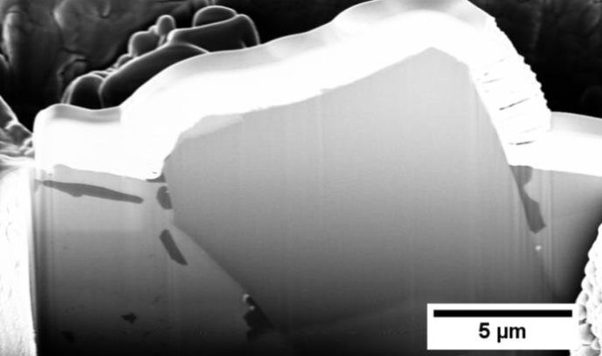
Lamella during liberation process using FIB
|
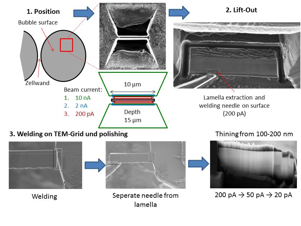
Lamella preparation process using FIB
|
|
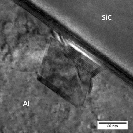
Bright field image of a spinell particle
|
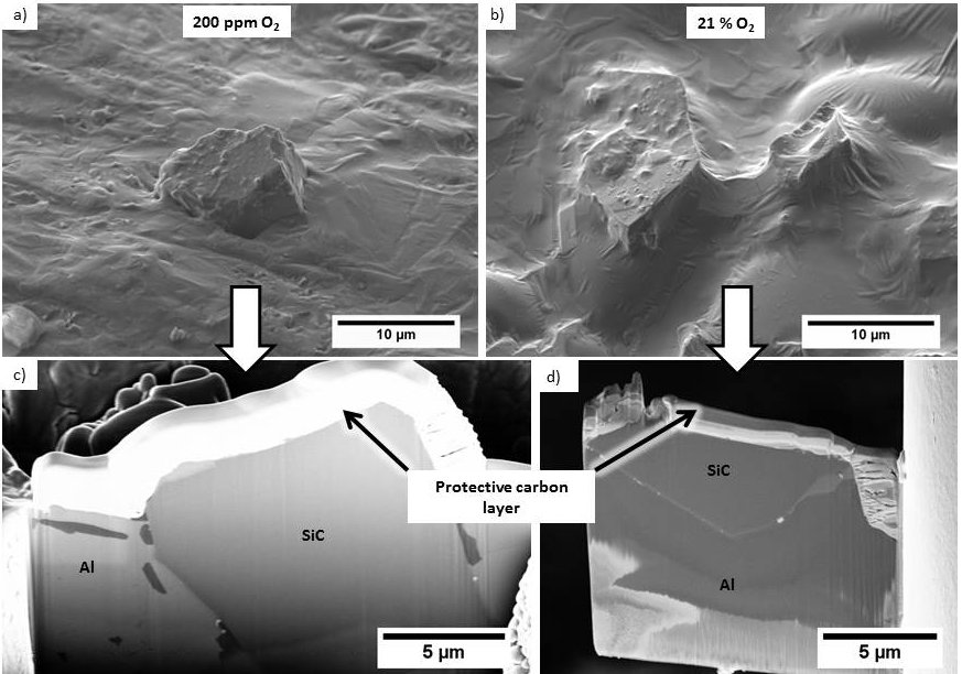
SEM image (SE2 detector) of SiC particles at the surface of an AlSiMg/SiC
film drawn at a) low oxygen and b) 21 % O2 as well as c) and d) their corresponding cross section (Inlens detector),
during preparation of TEM samples using FIB.
|
It is known, that oxygen is required to stabilise a film, but the influence of oxidation can also be analysed using electron
microscopy to accumulate a broader knowledge of the processes at the solid-gas interface. All used films were therefore pulled
at 10 mm/s with a 12 mm (in diameter) single wire frame. Starting with the electro-optical investigation using SEM, a
significant difference could be visualised. SiC particles of AlSiMg/SiC are only partly embedded into the surface if
the oxygen level was reduced, see Figure left a), in contrast to particles which are totally covered by an oxide
layer at ambient conditions, see Figure left b). If such particles were cut to fine lamella for a following TEM analysis,
the behaviour was even more concretised in cross section, see Figure left c) and d).
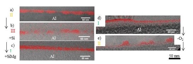
By a following study using EF-TEM, structural properties of the overlapping oxide layer could be defined. Oxide intense images
of Al/TiB2 and AlSi/TiB2(remnants of a ruptured film) at 21 % O2 indicate a discontinuous oxide layer (further called
oxide islands, red spots), which can be seen in Figure bottom a) and b). This characteristic structure exhibit a thickness of 0-20 nm.
The symbols of each image were established for a better comparison of the oxide layer structure to the stability of films of,
whereby I represents a stable, II a semistable (stable for small wire frame diameter or marginal oxygen concentration) and
III an unstable film. If Magnesium is added to the alloy, as for AlSiMg/TiB2, see Figure bottom c), the oxides transform
to a continuous layer of 20-35 nm in thickness. The type or amount of particles plays no role on the behaviour of the oxide
layer, see Figure 3d), whereby TiB2 particles were exchanged by SiC particles. However, if the oxygen content of the
atmosphere is reduced, again a discontinuous broken oxide layer of 0-35 and 0-15 nm in thickness
will form respectively, see Figure bottom e). Although the oxide thicknesses are quite close together, it can be concluded,
that only films containing Magnesium and pulled at a sufficient concentration of ambient oxygen, are able to form a
continuous layer of oxides of constant thickness.
All details can be found soon in: K. Heim et al., 2015, in work
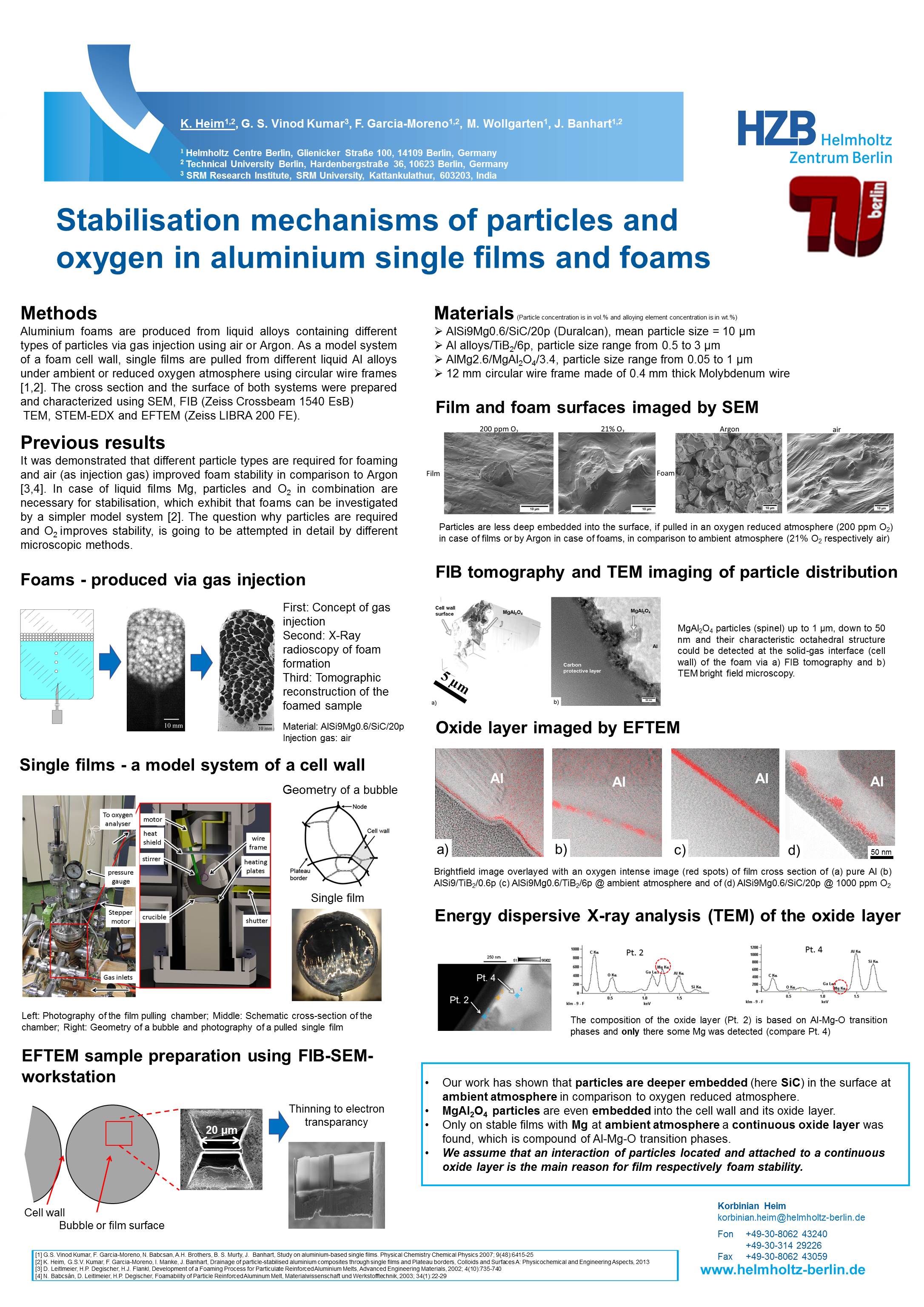
The following poster summarise stabilisation mechanisms of particles
and oxygen in aluminium single films and foams, which was presented at
the "Microscopy Conference 2013".